How To Power On A Battery-Operated Medical or IoT Device

Battery-operated, wirelessly-connected devices are becoming increasingly pervasive in today’s society. Driven forward by advancements in wireless and battery technologies, coupled with shrinking electronic components that consume less power and cloud-based services ready to collect, analyze and disseminate data, these devices are commonly found in consumer, medical and wearable devices as well as in commercial, and industrial applications.
Whether the device is a wearable continuous glucose monitor (CGM), an ingestible or implantable medical device, or a smart home device, asset tracker or environmental monitor, all share the common requirement of small size, long life, reliability and ease of use. One of the major problems faced by designers of these products is powering on the device when needed.
Powering on an IoT device only when it is needed (or keeping it powered down before it is deployed) is vitally important because designers want to use the smallest, lowest cost battery possible. For this reason, extending battery life is always a design goal; battery drain must be minimized during use as well as before it has been powered on.
One popular example is the continuous glucose monitor (CGM) prescribed to a Type 1 or Type 2 diabetic. This device adheres to a patient’s body, continuously monitoring his/her glucose level. Resulting data is wirelessly transmitted to the patient, doctor and/or insulin pump. CGM’s must be very small, “water proof”, easy to attach and have a reasonably long life before they run out of battery power.
There are three basic options for powering on these devices at the point of use or deployment. For each of these options, essential variables for consideration are battery current drain, size, ingress protection and user friendliness.
The first “Power On” option is electromechanical or the common “switch.” This option is the means for powering on most battery-operated electronic devices such as laptops and phones. Although switches come in many forms, (e.g.; push button, slider or toggle) they operate on the same principle of opening and closing a mechanical contact to allow current to flow (when closed) or completely prevent it from flowing (when open). With regard to the first consideration of current drain, the electromechanical switch is highly efficient because it is a passive device which consumes no power. However, in terms of size, mechanical switches are a poor option, especially given the size constraints of many wearable, ingestible and implantable medical devices and other small IoT devices. In terms of ingress protection, (or need to have a device that is impermeable to water and humidity) mechanical switches are not the best option as designing a switch that can be mechanically moved by the user into on/off positions while maintaining impermeability is challenging. Lastly, the consideration of user friendliness, or ease of use, rates poorly with mechanical switches for two reasons – first: since the user must actually take this step (and many need to be instructed to do so), the requirement for many devices is “out-of-the-box turn-on” – a clear conflict with manually operated switches. Secondly, a very small mechanical switch, necessitated by a very small device, could pose a problem for users’ ability to actually move the switch to the on position, thereby reducing usability. So, in summary, mechanical switches score highly in terms of current consumption but very low relative to ingress protection, size and ease of use.
Wireless power on is the second option to analyze. Because the devices already have wireless capabilities to transmit data, designers could technically use that same wireless capability to power on a device from a mobile phone app. From an ingress protection standpoint, powering on wirelessly is rated very highly. And, from a size standpoint, powering on wirelessly also rates highly as there is nothing more to add to the device for this functionality. However, from a current drain standpoint, wireless power on scores extremely low because a wireless receiver inside the device must be powered on to receive a signal to power on. For this reason alone, wireless power on is rarely used for devices that have stringent battery life requirements.
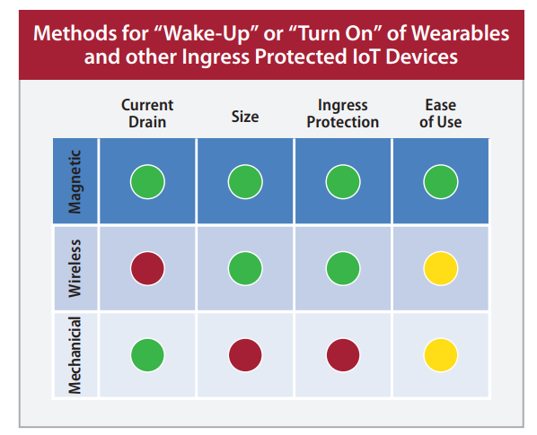
The third option is the use of a magnetic sensor inside the device to initiate the power on function. In this case, a magnetic field is applied to the sensor to trigger the power on. The magnetic field is typically produced by a magnet that is located within the product’s packaging or in an auxiliary component to the device (such as an applicator for a CGM). The magnetic field can also be applied by the user swiping across the device with a handheld magnet. Magnetic sensing scores very highly for ingress protection (because it is a “contact-less” method).
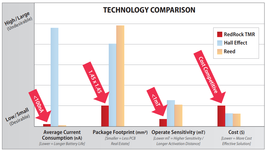
Magnetic sensing also scores very highly in ease of use – especially when the magnet can be embedded in the device packaging (enabling “out-of-the-box power on”) or in an auxiliary component to the device (e.g; an applicator). Sometimes the device, itself, is designed as two components that must be connected together at the time of deployment. In terms of current drain and size, the desirability of magnetic sensing depends entirely on the magnetic sensing technology. Older, more traditional magnetic sensing technologies types were either small in size, but high in power consumption (Hall Effect) or large in size with zero power consumption (reed switches). However, many new devices are designed with a newer magnetic sensing technology called Tunneling Magnetoresistive (TMR) which offers both very small size (as small as an LGA-4) and extremely low power consumption, similar to the reed switch. In effect, TMR magnetic sensors offer the “best of both worlds.”
With the current onslaught of new devices designed to make life easier, safer, contact-less and/or operable remotely, electronic designers are having to adopt new technologies to keep up with the evolving requirements of battery-operated wearables, implantables, ingestibles and other IoT devices. In terms of best capabilities relative to small size, lower power consumption, ingress protection and ease of use, magnetic sensors – and TMR sensor technology in particular – are helping to make “impossible” designs possible.
For further information, including advice on battery types not included in this report, please contact: redrock@cotorelay.com or visit www.cotorelay.com.
How Does a TMR Sensor Operate?
The sensor itself is a three pin device – power, ground and digital output (push/pull or open drain). The power supply, Vdd, can range from 1.7V to 5.5V. The output goes LOW when the magnetic field at the sensor reaches the operate field threshold of the sensor, which can be as low as 9 Gauss or 0.9 milliTesla. The output goes HIGH when the field is reduced to below the release field threshold of the sensor (about 5 Gauss for a 9 Gauss operate sensor). It’s also worth noting that a 9 Gauss operate threshold of a TMR magnetic sensor allows for pairing with very small, low-cost magnets – in some cases, even commonly available plastic-bonded ferrite magnets.
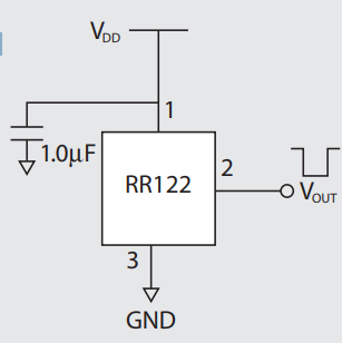
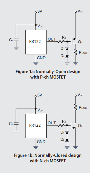
Designing with TMR, there are three very simple ways to implement a power on circuit. The first is to connect the push pull output to a wake up pin on the microcontroller. The second is to connect the open drain output directly to the IC you want to power; this method is restricted to the maximum current a TMR sensor can sink, which is 20mA. For higher currents, a third method can be utilized; connect the sensor output to MOSFETs. This can be done to implement normally open and normally closed operation.
Tunneling Magnetoresistance
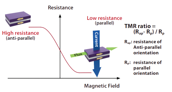
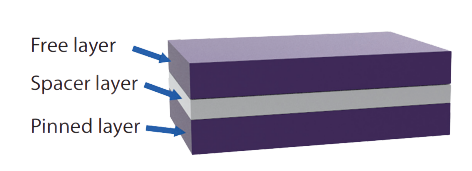
A tunneling magnetoresistance (TMR) sensor is comprised of a magnetic tunneling junction (MTJ) element and CMOS circuitry. A MTJ element is a multilayer, thin-film stack which is composed of a sandwiched structure with a free layer, a spacer layer, and a pinned layer. (Fig. A) The spacer layer (made of dielectric oxide material) separates the ferromagnetic free layer and pinned layer from one another. The electrons moving within the free layer and pinned layer planes are unable to cross the spacer layer to the opposite side. However, if magnetic flux is applied to the MTJ, the magnetism direction of both ferromagnetic layers can be switched between anti-parallel and parallel orientation. In the parallel magnetism orientation, electrons can make a quantum leap to tunnel through the spacer layer; a tunneling current will be observed across the MTJ structure and the relative resistance of the MTJ will be changed between high resistance and low resistance.
The difference of relative resistance is the “TMR ratio” (Fig. B). TMR ratio can reach approximately 40% at room temperature, and it is comparatively larger than other MR technologies. This feature, which is a implementation of quantum physics, makes the ingenious TMR sensor possible, with higher sensitivity, lower power consumption, and more stable characteristics.