How to Replace a Hall Effect Sensor with a TMR Sensor

Do you have an application that currently uses a Hall Effect sensor and want to replace it with a TMR sensor? In circumstances where Hall Effect sensor lead times remain extremely long due to ongoing supply shortages, RedRock® TMR sensors can be a welcome alternative, as they are readily available – either in stock or with very short lead times. Popular applications may include home security, metering, battery-powered medical devices, industrial automation, liquid level measurement, consumer products, instrumentation and IoT devices.
Coto Technology’s Applications Engineers have extensive knowledge of magnetics and magnetic sensing and are available to discuss your application needs and provide suggestions on how to incorporate a RedRock® TMR sensor into your application in the most optimal way. Contact us at RedRock@Cotorelay.com.
For a summary of the tips shown in this document, as well as additional available resources, please check the Appendix at the end of this document.
See Related Video “Replacing Hall Effect Sensors with TMR Sensors – How and Why” (link: https://youtu.be/wz2ZO3kSfNE)
1 Introduction
In the world of magnetic sensing, Tunneling Magnetoresistance (TMR) sensors have proven to be a great alternative to the more traditional Hall Effect sensors, for a variety of reasons.
- A TMR sensor’s power consumption can be less than 100nA, which translates into a longer lifetime in battery powered applications.
- TMR sensors can be more sensitive than Hall Effect sensors; because TMR sensors can operate with a weaker magnetic field a smaller, less costly magnet can be used in an application and/or a greater distance can exist between the sensor and magnet.
- Like many Hall Effect sensors in the market, TMR sensors are available in an industry standard SOT-23 package, with both technologies having the same pinout. This means that a TMRsensor can be dropped into an application that uses a Hall Effect sensor without the need for any electrical changes to the printed circuit board.
Given these benefits, more and more engineers are using TMR sensors in place of the Hall Effect sensors formerly used in their applications.
In this document, we’ll cover how to replace a Hall Effect sensor effectively with a TMR sensor incurring minimal modifications. Specific topics will include:
- Magnetic Axis of Sensitivity
- Proper Orientation of a Magnet with a Magnetic sensor
- Specific Application Examples and Scenarios
2 Magnetic Axis of Sensitivity
One point that needs to be considered when replacing a Hall Effect sensor with a TMR sensor is that each technology operates with a different magnetic Axis of Sensitivity. Although this can be confusing to design engineers at first, it should not discourage them from using TMR sensors in their applications.
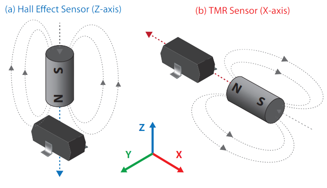
The Axis of Sensitivity refers to the direction that the magnetic field needs to have inside the sensor package (at the sensing element) for the sensor to respond to it. Figure 1 shows the orientation of the Axis of Sensitivity for a Hall Effect sensor and a TMR sensor, both in an SOT-23 package. Given the coordinate frame shown in that Figure, a Hall Effect sensor operates with a magnetic field oriented along the Z-direction, whereas a TMR sensor operates with a field along the X-direction. The figure also shows the preferred way to orient a magnet with respect to the sensor package for each technology, which consists of aligning the magnet’s polarization axis with the sensors Axis of Sensitivity. This way of orienting the magnet produces the strongest possible flux density at the sensor for a given distance between the magnet and sensor. In most applications that use Hall Effect sensors, the magnet is positioned with the preferred orientation shown in Fig 1(a). And, even when applications would greatly benefit from changing to TMR, design engineers may be reluctant to make the switch, thinking that they need to completely redesign their application to accommodate a TMR sensor with the orientation shown in Fig 1(b). That is not necessarily the case, and these preferred orientations are not the only ones that will ensure proper operation of the sensor. By understanding what is required to activate a magnetic sensor and how to orient a magnet to achieve those requirements, one can replace a Hall Effect sensor with a TMR sensor with minimal modifications.
3 How To Orient a Magnet With a Magnetic Sensor
Regardless of how a magnet is oriented with respect to a magnetic sensor, there’s two conditions that need to be met for the sensor to respond to it:
- The field must have a component that aligns with the sensor's axis of sensitivity. In the case of a TMR sensor, with X-axis sensitivity, we can refer to this field component as Bx.
- The magnitude of this Bx component needs to be strong enough for the sensor to respond to it. For example, in the case of a Digital Magnetic Sensor (where the output changes between HIGH and LOW), the Bx component needs to exceeded sensor’s magnetic operate threshold (BOP) for the output to change state.
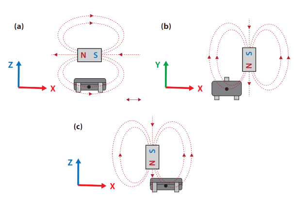
Figure 2 shows additional examples of magnet orientations that can activate a TMR sensor.
4 Replacing a Hall Effect Sensor With a TMR Sensor Assuming Preferred Hall Effect Magnet Orientation
Note how option (c) in Figure 2 is very similar to the preferred orientation of a Hall sensor, only that the magnet isn’t centered above the sensor package. Instead, it has an offset along the X-axis.
To understand how a TMR sensor can work with this orientation, let’s look at the magnetic field surrounding a magnet that has its polarization axis aligned with the Z-axis, like in Figure 3. As denoted by the dotted lines, the magnetic field exits the magnet’s North Pole and loops around to return via the South Pole. As a result, the magnetic field has many different orientations at different points around the magnet.
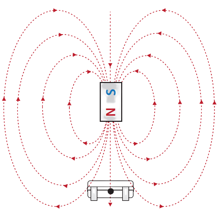
Note how the magnetic field along the polarization direction is perfectly oriented along the Z-axis, which means there’s no X-axis component. If a TMR sensor is positioned such that its sensing element is aligned with the polarization axis (as shown in Figure 3) the sensor will not respond to the magnetic field. However, if the sensor is moved along the X-axis, it will be positioned in a region where the magnetic field has a Bx component, as shown in Figure 4. As mentioned previously, if the Bx component is sufficiently strong, the TMR sensor will respond to it.
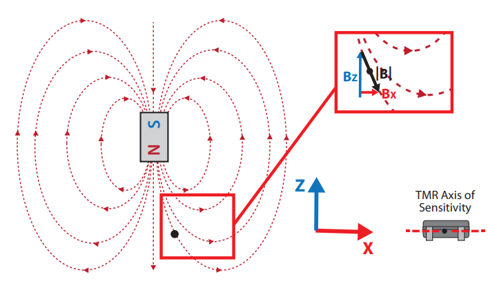
Note that the sensor doesn’t need to be placed in a location where the field is fully aligned with the X-axis. Having a strong enough Bx component will be enough. And, if the required sensor response is Omnipolar (the sensor activates with either a North or a South polarity) the offset can be applied in either direction along the X-axis. The required offset for a TMR sensor to work can be as small as 2-3millimeters, though this will depend on factors such as: the sensor's sensitivity, distance between magnet and sensor (along the Z-axis)and the magnet specs (size, grade, shape).
The required offset for a TMR sensor to work can be as small as 2-3 millimeters, though this will depend on factors such as: the sensor's sensitivity, distance between magnet and sensor (along the Z-axis)and the magnet specs (size, grade, shape).
One more thing to note here is that for small offsets from the center axis, the Bx component will be much smaller than the BZ component. A higher sensitivity TMR sensor can compensate for the difference inthe magnitude of the flux density. For example, if the initial design uses a Digital Hall Effect sensor that activates with 40 Gauss, it could be replaced with a Digital TMR sensor that activates with 9 Gauss.
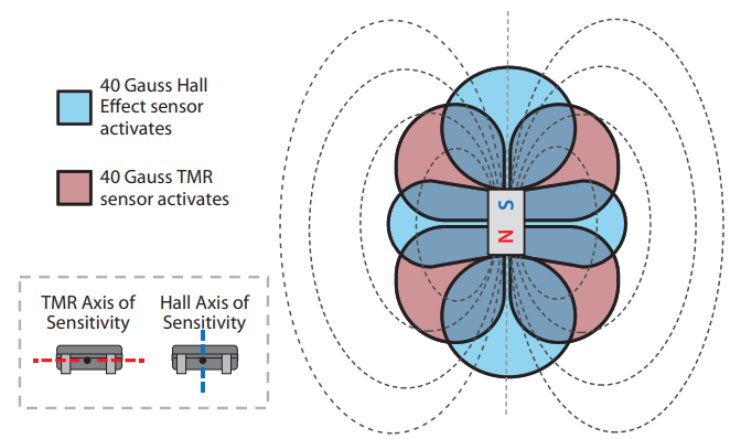
Figures 5 and 6 show a cross section of a cylindrical Neodymium magnet that has a diameter of 3.175mm and a length of 6.35mm, and has its polarization axis parallel to the Z-axis. Around the magnet are two sets of lobes. In Figure 5, the blue lobes represent the regions where the BZ component exceeds 40 Gauss, whereas the red lobes are where the Bx component exceeds 40 Gauss.
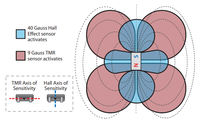
In Figure 6, the blue lobes still represent where BZ exceeds 40 Gauss, but the red lobes represent where Bx exceeds 9 Gauss.
The goal of these diagrams it to illustrate how much overlap there is between the lobes of each sensor type (Hall Effect, TMR) and thus how much flexibility a user can have when replacing a Hall Effectsensor with a TMR Sensor, especially if selecting a TMR sensor with a higher magnetic sensitivity.
Now, let’s look at various Application Scenarios to see how the outlined principles come into play and what is required to replace a Hall Effect sensor by a TMR sensor.
5 Application Example Scenarios
Depending on the needs of a given application, a magnetic sensor may be required to sense a magnet that is moving linearly, rotating, etc. In this section, we will look at scenarios where a Hall Effect sensor is paired with a magnet following the preferred orientation shown in Figure 1, and what steps can be taken to replace it with a TMR sensor.
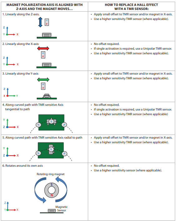
5.1 Magnet Moves Linearly
Figure 7 shows a series of diagrams each containing a sensor and a magnet. In all diagrams the magnet is oriented with respect to the sensor package in the same way (i.e., polarization axis is orientedalong Z-axis). The top two diagrams show the magnet moving along.
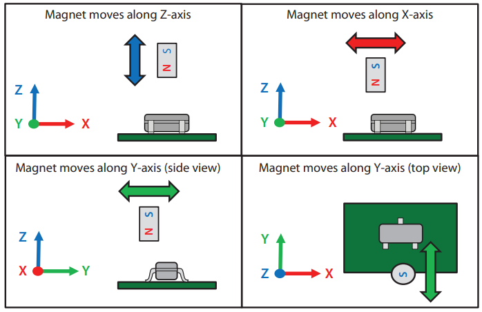
the Z and X-axis, and the bottom two diagrams correspond to a magnet moving along the Y-axis.
In the case of movement along the Y and Z axes, the key to using a TMR sensor is to shift the magnet and/or sensor along the X-axis as was described in the previous section. This will ensure that, at every point of the magnet’s movement, its polarization axis will not be centered above the TMR sensor’s sensing element.
In the case of a magnet with this orientation moving along the X-axis,Figure 8(a) shows the flux density components that would be seen by a Hall Effect (Z-axis) and a TMR sensor (X-axis), and Figures 8(b),8(c) and 8(d) show the output responses of a 30 Gauss Omnipolar Hall Effect sensor, a 9 Gauss Omnipolar TMR sensor and a 9 Gauss
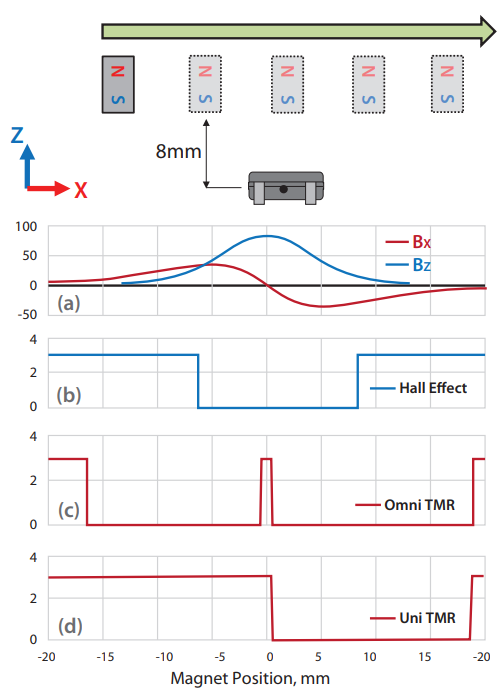
Unipolar TMR sensor, respectively. The magnet is an N42 grade, cylindrical magnet with a diameter of 1/8” (3.175mm) and a length of¼” (6.35mm) that is positioned at 8mm (along the Z-axis) from a magnetic sensor. All sensors are assumed to have an Active Low response, meaning that the output goes LOW when exposed to a magnetic flux density that exceeds each sensor’s respective Operate thresholds.
A Hall Effect sensor would see a Z-axis flux density component that increases and then decreases as the magnet passes by. This flux density would reach a peak when the magnet is directly abovethe sensor. This flux density would have a single polarity (North or South, depending on how the magnet is oriented). Thus, if a digital Hall Effect sensor with an Omnipolar is used, it would see a single activation with each pass of the magnet. In other words, the sensor’s output would change state at some point while the magnet approaches it (and the flux density exceeds the Operate threshold), and it will revert to the original state once the magnet leaves (flux density drops below Release threshold). The blue curve in Figure 8(a) shows the BZ component of flux density as a function of magnet position and Figure 8(b) shows the response of a Hall Effect sensor to that flux density profile.
The TMR sensor, on the other hand, would see an X-axis flux density component that has a positive and a negative peak, as shown by thered curve in Figure 8(a). These peaks represent different directions of the flux density at the sensor. Given this, an Omnipolar TMR sensor would activate and deactivate twice as the flux density exceeds the sensor’s Operate threshold for each polarity. This can be seen in Figure 8(c). For applications that are using a Hall Effect sensor but may being switched to a TMR sensor, this double activation may beun desirable, especially if the processing unit that reads the sensor’s output is configured to look for a single activation/deactivation. One potential solution to this is to use a Unipolar TMR sensor, which only responds to a single polarity (North OR South) as shown in Figure 8(d).
5.2 Magnet Moves Along a Curved Path
Another configuration seen in magnetic sensing applications is one where the magnet passes by the sensor while moving along a curved path, as shown in Figure 9. Both diagrams show a top view of a PCB with an SOT-23 magnetic sensor on it and a magnet passing above it.
In the scenario shown on the left, the sensor will see flux density components that are very similar to those seen in the case where the magnet moves linearly along the sensor’s X-axis, and a Hall Effect and a TMR sensor would have similar responses to those shown in Figure 8. An Omnipolar TMR sensor would have two activations, whereas a Unipolar TMR sensor would only see one.
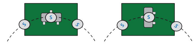
Along the same lines, the scenario shown on the right in Figure 9 will produce similar results to the case where the magnet moves linearly along the Y-axis. The same suggestion mentioned in the previous section applies: if using a TMR sensor, apply an offset along its X-axis for it to successfully be activated by the passing magnet.
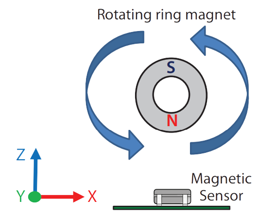
5.3 Rotating Magnet/Metering Applications
Now let’s consider a magnetic sensor positioned near a diametrically polarized rotating magnet, as shown in Figure 10. This is a common configuration in applications like utility metering and basic motor encoders used to estimate speed and direction of rotation. As this magnet rotates, it creates an alternating magnetic field at the sensor. If a digital magnetic sensor is used in this scenario, its output will be comprised of a train of pulses caused by repeated activations and deactivations of the sensor as the field changes. This train of pulses can be used to calculate the rotation frequency and multiple sensors can be used to determine the direction of rotation [1]. Alternatively, ananalog sensor can be used to obtain a time-varying voltage output that is proportional to the alternating magnetic field, but for purposes of this discussion, we will focus on a digital sensor.
To illustrate how a Hall Effect and a TMR sensor would respond to the field generated by a rotating magnet Figure 11 shows two diagrams hastwopoleswith a ring magnet, above a magnetic sensor. The magnet has two poles, an outer diameter of 6.35mm, an inner diameter of 3.175mmand a length of 6.35mm and the sensor’s center is positioned 17mmfrom the rotating axis of the magnet.
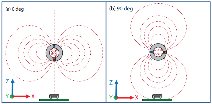
In the image on the left the magnet’s polarization axis (and thus the magnetic field line at the sensor) is aligned with the Z-axis. In the image on the right, which shows the magnet being rotated by90 degrees, the polarization axis and the flux line at the sensor are aligned with the X-axis. A Hall Effect sensor would be activated in the first position, but not in the second one.
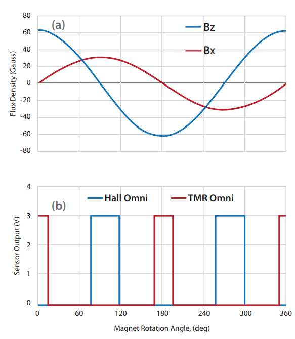
We can take this one step further by graphing the Bx and BZ components produced by the magnet at the sensor’s center as a function of the rotation angle of the magnet (See Figure 12(a)). Note how both Bx and BZ have the same sinusoidal profile, but Bx is shifted by 90 degrees and has a smaller magnitude than BZ. As mentioned previously, this can be compensated for by using a higher sensitivity TMR sensor. Other than this, there’s no required change to the positioning of the magnet and/or the sensor, given that both Bx and BZ components have the same pattern and would produce the same number of activations/deactivations in each sensor type with each rotation, as shown in the graph in Figure 12(b). The Hall Effect and TMR sensor outputs shown are assumed to have the same sensitivities as the graphs in Figure 8: 30 Gauss for the Hall Effect and 9 Gauss for the TMR sensor. Note: For simplicity, the Hall Effect and TMR sensor responses in Figure 12 are assumed to be Omnipolar. However, in rotation counting applications, it is common to use a magnetic sensor with a Bipolar response, as described in [1]. With that output response, the sensor would see the same flux density components shown below, but instead of two pulses per each magnet rotation a Bipolar sensor produces only one.
Conclusions
- Even though Hall Effect and TMR sensors operate with different Axes of Sensitivity, replacing a Hall Effect with a TMR sensor does not always require a major redesign of the application.
- Understanding the Axis of Sensitivity of each technology and the magnetic field pattern created by a magnet are key in determining how to replace a Hall Effect sensor with a TMR sensor effectively. This makes it possible for design engineers to benefit from TMR’s features without having to spend too much time and/or money in redesigning a product.
- Different applications can employ magnets that move linearly, along a curved path or that rotate about their own axis. Though this is not a comprehensive list, the scenarios shown in this document are the most common ones.
- Coto Technology’s Applications Engineers can work with youto provide guidance on how to incorporate a TMR sensor into your design.
Additional Resources
NOTE: RELATED VIDEO “Replacing Hall Effect Sensors with TMR Sensors - How and Why”( https://youtu.be/wz2ZO3kSfNE )
APPENDIX: Summary of various scenarios with different magnet movements